Cable Adapter HP49-PC
See also Make a Cable
 Español

This page was originally made by Alejo Chong Jimenez, from Mexico,
and published in his page EXPANSION CEREBRAL.
It is published in Area48.com under permission.


Enrico Carta wrote a document, where he expalins how to make a cable for HP49. He propose very methods, that are indeed good, but it is needed to find a 10 pins connector, with two rows of pins separated of 2.1 mm. As we know, it is too hard to find, at least here in Mexico and I think that also in other countries. Another option is to cut the cable that comes with HP49G, but that, I am sure, you don't wish to do.

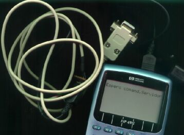
In this document I present another idea beased in the ones previously presented by Enrico Carta. Indeed, it is not a cable to cennect directly the HP49 to the PC, but an adapter to connect HP49 to the PC, using the cable that come together with the HP49G pack.


Stuff you will need:
Click here to see the stuff and tools
  1. a cable of 4 wires
  2. a DB9-F; that is a DB9 female connector like the one of your mouse,
    easily found in any electronic shop.
  3. adhesive/insulation tape
  4. four pins that adjust in the orifices of the HP49 port
  5. a little piece of PC board without copper in both sides
  6. half metter (20 inches) of weld
  7. a piece of (thin) sandpaper
  8. Soldering Iron
  9. a multitester to check the conductivity of the cable.

You must to execute the following operations:
  1. made the PC board of 5 holes separated of 2 milimetres each other.
  2. Introduce the pins in the PC board. Attention! They can't touch one another.
  3. weld every wire at every corresponding pin of the PC board.
  4. isolate the pins with the adhesive/insulation tape.

    paso 4
  5. Connect the connector you have made in the row inferior of the cable that come with the HP49

    Paso 5
  6. in th other side of the cable, weld the wires as they are shown in the scheme below.
    You can use the multitester to check.


    Below the description of the pins as made originaly by Enrico Carta:

    2.1. HP49G-10pin Connector

    • Connectors are seen in front view, with the HP logo on their top.
    • The male connector in the upper-side of the calculator is seen in front view (LCD screen on the top) in this way:
     PINOUT DESCRIPTION:
      6. SHIELD
      7. TX (TRANSMITTED = CALCULATOR OUTPUT)
      8. RX (RECEIVED = CALCULATOR INPUT)
      9. GND
    

    2.2. DB9 Connector (RS-232).


    PINOUT DESCRIPTION:
      2. DATA-IN (COMPUTER INPUT = DATA FROM CALCULATOR)
      3. DATA-OUT (COMPUTER OUTPUT = DATA TO CALCULATOR)
      5. GND
    

    As we can see the PIN 6 of the calculator is connected to the ground of the DB9, i.e. , the metalic body that encloses the connector. As it is too smoot it is best to use a sandpaper to make some scratches on it,
    to weld it easily.

  7. Finally, isolate and put the protective cover.

     Terminado


Back to Top
End of File